What is CNC milling? A complete guide on processes, applications, benefits, and limitations
Many of the technologies we interact with daily, from tech accessories and automobiles to planes and hospital equipment, are made possible, in part, by CNC milling. CNC (Computer Numerical Control) milling is a manufacturing technology that plays an indispensable role in technological advancements, enabling innovation through rapid prototyping and making products widely available through batch production. This fast, accurate, and versatile manufacturing process is vastly popular across numerous industries for producing a wide range of products. So, what is CNC milling, how does it work, and is it the right technology for your application?
This guide comprehensively explores everything you need to know about CNC milling, from the process to how CNC milling machines work. The guide also delves into the applications, benefits, and limitations of CNC milling.
What is CNC milling?
CNC milling is a subtractive manufacturing process in which a computer-controlled rotating cutting tool selectively removes portions of a block of material to form a desired object. Milling technology existed as a manufacturing process before the incorporation of CNC (Computer Numerical Control). In this technology, machine operators manually control the movement and direction of the rotating cutting tool and workpiece to produce a part, relying on drawings of the part. This process is slow, error-prone, and requires highly skilled operators.
The integration of computers transforms CNC milling-machining into a fast, precise, and highly accurate process. A computer precisely controls the speed, movement, and orientation of the cutting tool and workpiece, leaving minimal room for error.
CNC milling is a subset of CNC machining services, a broadly defined manufacturing process that includes CNC turning, CNC routing, and CNC drilling. CNC machining describes technologies that utilise computer-controlled tools to carve out portions of a block of material to create a part.
How does CNC milling work? The CNC milling process
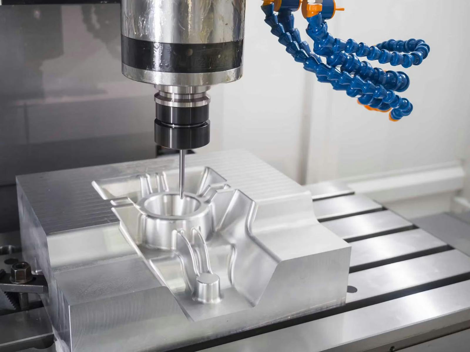
Various types of CNC milling operations and machines exist. However, they all follow the same working principle. A motor-powered spindle drives a rotating cutting tool that selectively removes material from a workpiece positioned on a worktable below or beside the tool. The spindle and worktable move in preprogrammed directions to enable the cutting tool to reach different areas of the workpiece. These movements are controlled by the machine's processor based on a given set of commands and are executed by moving mechanical feed mechanisms in the milling machine.
The CNC milling process, from conceptualisation to the finished product, typically comprises five main steps.
- Creating a CAD (Computer-Aided Design) model
- Converting the model from CAD to machine
- Setting up the milling machine
- Executing the CNC milling process
- Post-processing and finishing
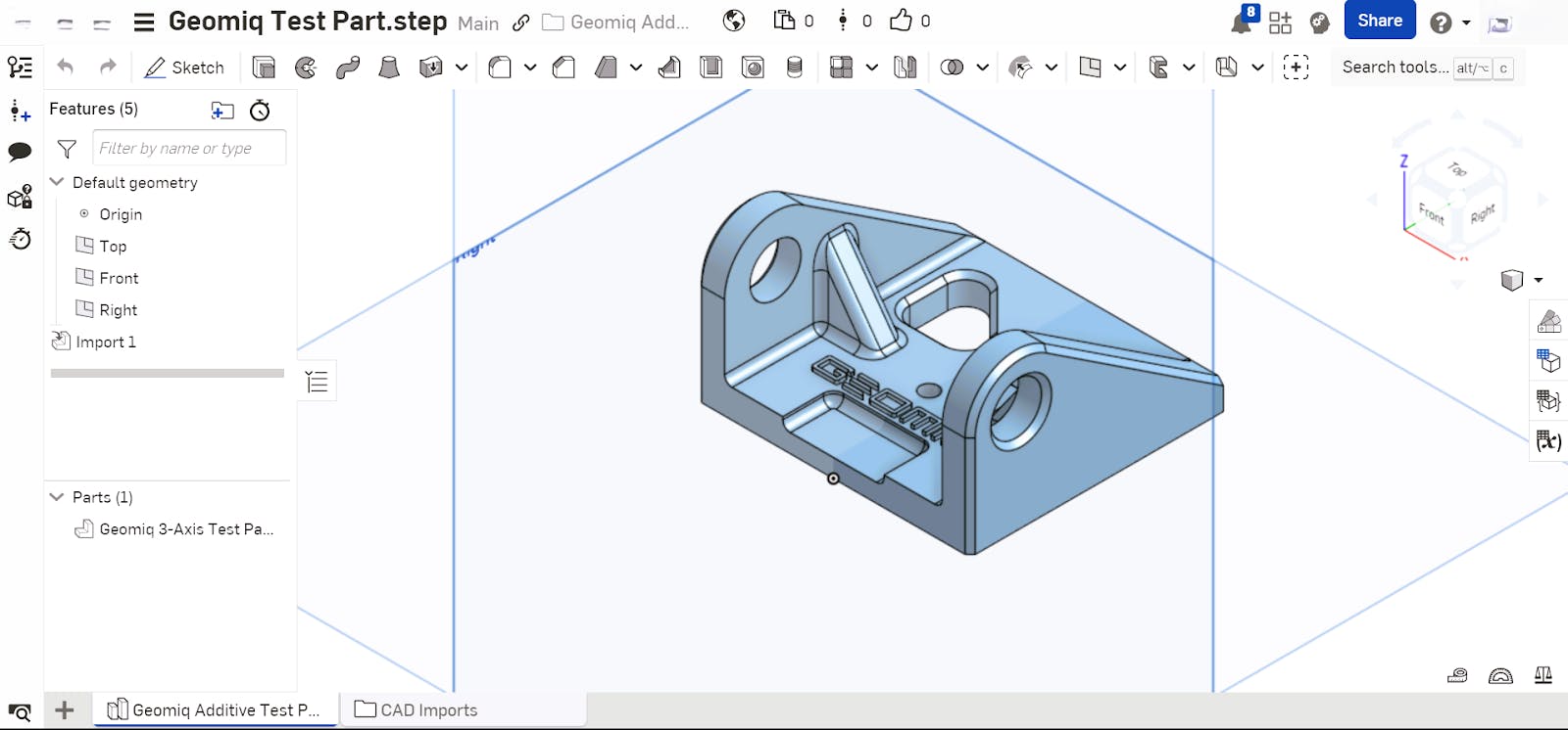
Creating a 3D CAD model
The first step in the CNC milling process is using CAD software to create a 3D model of the part.
Designers create a replica of the object, accounting for dimensions, tolerances, and materials. An important aspect of the design phase is Design For Manufacturing (DFM), the process of optimising a model design according to specific guidelines to ensure seamless and cost-effective manufacturing. DFM for CNC milling covers tolerancing, size & geometry limitations, and feature recommendations. See our DFM guide to learn more about optimising designs for manufacturing. Upload your designs to our instant quoting platform to receive complimentary DFM. After creating the model, the designer saves and exports the file in CAD format.
Converting from CAD file format to machine language
CNC milling machines do not directly read and interpret 3D models in CAD format. Specialised CAM (computer-aided manufacturing) software programs must first convert the CAD files into a CNC machine-readable programming language known as G-code (Geometric code). The CAM software analyses the imported 3D model and generates a corresponding set of commands that the CNC milling machine follows to produce the desired object.
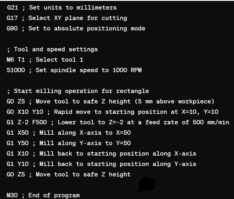
The G-code dictates the movement, orientation, speed, and feed of the cutting tool and worktable, progressively controlling these parameters until the object forms. Additional commands generated by the CAM software control other aspects of the CNC milling process, such as machine start and stop and flow of cooling fluid. The engineer exports the G-code from the CAM to the CNC machine.
Setting up the CNC milling machine
After importing the G-code, an operator sets up the machine for the specific CNC milling operation. The operator attaches the appropriate CNC milling tool to the spindle, securely fastens the workpiece to the machine's worktable, and orientates the planes, axes, and directions. Next, they set up any required additional tools, fixtures, and systems, such as a cooling system.
Executing the CNC milling process
After setting up the machine and workpiece, the operator switches on the machine, and the milling process begins. From this point on, human intervention is only required if a problem arises. The CNC milling machine executes consecutive lines of code, progressive cutting out pieces of the workpiece. Depending on the machine and milling operation, the cutting tool moves into a stationary workpiece, the workpiece moves into a stationary cutting tool, or they both move intermittently relative to each other. The cutting tool rotates at high speeds of thousands of revolutions per minute, cutting away at the workpiece on contact. These processes repeat until the desired object forms.
Post Processing
Postprocessing is optional in the CNC milling process. However, it is commonly used to bring finished CNC milling parts to a desired final state. Processing may be aesthetic or functional and varies with materials. The part below has undergone bead blasting and anodising type II.

CNC milling post-processing options include:
- Surface finishing: Deburring, polishing, blasting powder coating, and painting.
- Coating: Galvanizing (zinc), electroplating (chrome, nickel), and anodizing.
- Treatment: Quenching, tempering, and normalising.
CNC milling design considerations
Tolerance
CNC milling-machining is a highly precise process. However, it is impossible to manufacture a part with absolute perfection. While CNC milling can create parts with over 99% accuracy, certain applications require that sub-1 % be taken into consideration, thus requiring tolerances. Tolerances are allowable variations from the specified dimensions and shape of a machined part that will still enable the part to function as intended. Designers specify tolerances during the design phase. However, the maximum tolerance that can be achieved depends on the manufacturing process. Tolerance standards for subtractive manufacturing are defined by ISO 2768 and ISO 286. For CNC milling operations and machines, standard tolerances are
- Milling (3-axis): ± 0.005″ or 0.13 mm
- Milling (5-axis): ± 0.005″ or 0.13 mm
- Engraving: ± 0.005″ or 0.13 mm
- Rail Cutting Tolerances: ± 0.030″ or 0.762 mm
- Screw Machining: 0.005″ or 0.13 mm
The table below shows standard tolerances for linear dimensions.
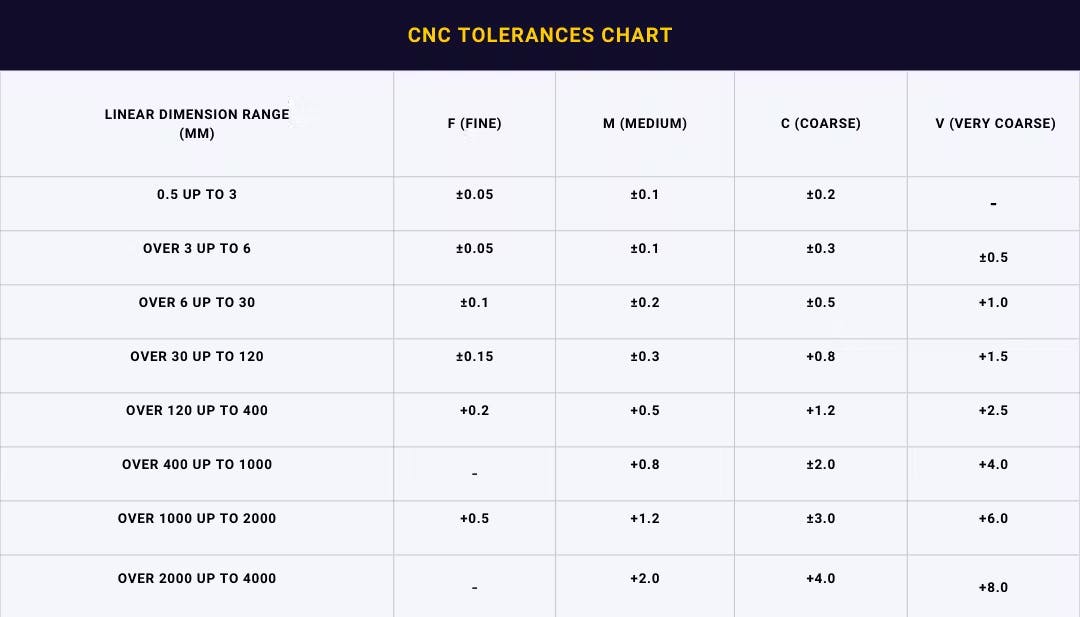
Note that tight tolerances require precision machining, which increases machine time, effort, and cost. Only use tolerances when necessary. See our CNC machining tolerances guide to learn more about tolerances, tolerance standards, and the process of tolerancing.
Geometries and features
When designing parts for CNC milling, it is important to account for the limitations of the machines. The following are some features and geometry considerations for CNC milling.
- Avoid curved holes. It is impossible to create these features as CNC milling tools are rigid and cannot bend through a part.
- Avoid undercuts. Similar to curved holes, undercuts are impossible to reach features.
- Avoid excessively thin, high walls. CNC milling-machining subjects parts to high vibrations. Thin, high walls are susceptible to breaking during machining.
- Design internal edges with radii. Cutting tools are typically circular, making it impossible to create straight internal corners.
- Size limitations for CNC milled parts are determined by milling machines. We recommend a maximum size of 1.2 mm x 1 mm x 1 mm.
Consult our CNC machining design guide for more comprehensive information on designing for CNC machining. Contact Geomiq to get help from seasoned experts on selecting the best materials for your part.
What is a CNC milling machine? Machine parts, types, and milling terminologies
A CNC milling machine is simply a computer-controlled milling machine. To understand how a CNC milling machine works, it is essential to understand the parts that comprise the machine and their functions.
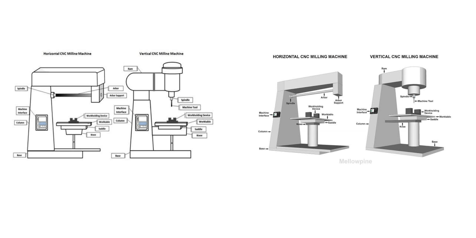
While a wide variety of CNC milling machine types exist, they all have a set of fundamental components that form the central framework of the machine. They also have certain variations in parts. The image below shows the different parts of a horizontal and a vertical CNC milling machine.
- Motor: The motor generates the rotational force that powers the cutting tool. The motor's speed is variable and is controlled by the machine's processor.
- Spindle: The spindle connects the cutting tool to the motor and holds it securely in place.
- Cutting tool: The cutting tool attaches to the spindle and is responsible for carving the workpiece. There are numerous sizes, shapes, and types of cutting tools for different CNC milling operations.
- Machine head: The machine head houses the spindle and the cutting tool. In some models, the machine head is capable of motion to varying degrees and in various axes. It may also be stationary. Models with head movement have mechanical features, such as a ram and an arbour, that facilitate these movements.
- Ram: The ram is a feature of vertical milling machines. It connects to the spindle and provides vertical movement in the Z axis.
- Arbour: The arbour is a feature of horizontal milling machines. These are machines in which the cutting tool moves horizontally. The arbour is a shaft along which the cutting tool moves.
- Worktable: The worktable holds the workpiece during the CNC milling process. It typically features holding fixtures that securely fasten the workpiece to the table. The worktable may be capable of various degrees of movement. Depending on the models, the worktable or machine head moves while the other remains stationary. Both the machine head and worktable may also move relative to each other. Models with movable worktables feature feed mechanisms, such as a saddle and a knee, that facilitate motion.
- Saddle: The saddle facilitates the worktable’s movement in the X-axis (sideways). It is located in between the worktable and the knee.
- Knee: The knee is located just below the saddle. It facilitates the movement of the worktable in the Z-axis.
- Computer and Machine Interface: The machine's computer is the brain. It receives the G-code files from an external computer and sends the commands to the m, effectively controlling all the machine's movements. The processor is typically embedded in the machine, with an external-facing machine interface providing a point of interaction between the operator and the CNC milling machine.
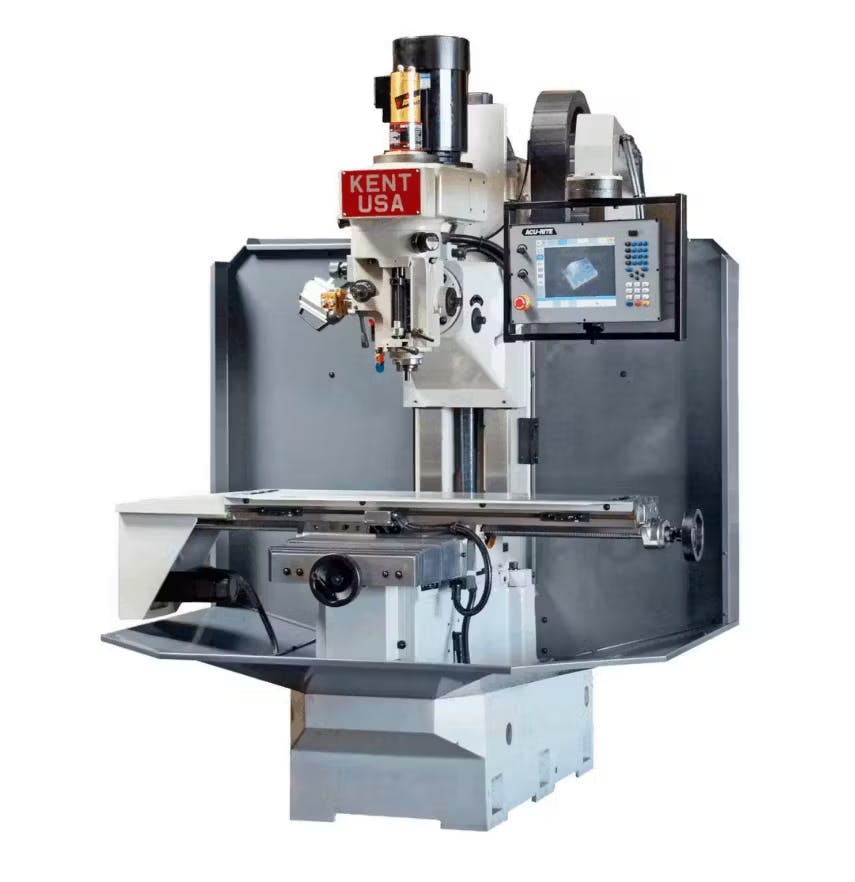
Note that while most CNC milling machines feature these parts, their builds, shapes, and sizes vary. The images below are a few examples of CNC milling machine builds.

CNC milling machine types
There are different types of CNC milling machines that vary by size, build, and cutting orientation. The most common classification for CNC milling machines is the number of axes in which the cutting tool and workpiece can move. According to this classification, there are three main types of milling machines: 3-axis, 4-axis, and 5-axis.
3-axis CNC Milling Machines
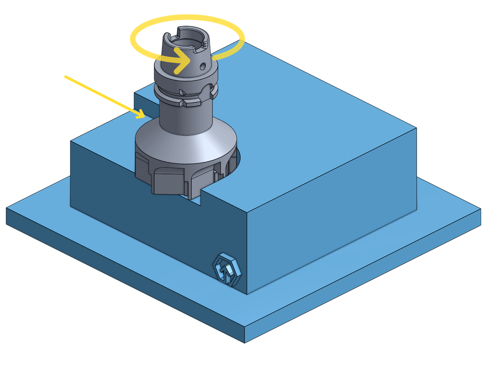
3-axis milling machines can move in three axes: the X (sideways), Y (back and forth), and Z (up and down) axes. The cutting tool, worktable, or a combination of both may execute the motion. The image below shows a CNC machine with 3-axis milling.

4-axis CNC Milling Machines
Four-axis milling machines move in three lateral axes (X, Y, and Z) plus an additional rotational axis. They are more advanced than 3-axis milling machines and can create more complex parts faster.
5-axis CNC Milling Machines
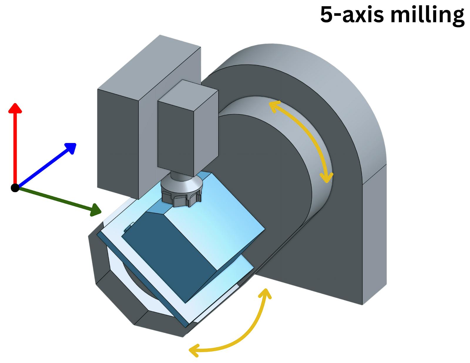
5-axis milling machines take it further with three lateral axes of motion and two rotational axes. The rotational motions may be on the vertical, lateral, or longitudinal axis. As with the other milling machines, the lateral and rotational movements may be carried out by the cutting tool, worktable, or a mix of both, depending on the machine. 5-axis CNC machining is highly advanced and capable of rapidly producing complex geometries. These machines are commonly employed in industrial CNC milling. The image below shows a CNC machine with 5-axis CNC milling machining.
CNC milling machines are also classified according to the parts executing the required motions.
CNC milling operations
CNC milling can produce a wide variety of features and shapes. This manufacturing technology achieves this through a series of specific motions and cutting techniques known as milling operations. The most common CNC milling machine operations are:
- Plain milling
- Face milling
- Angular milling
- Form milling
CNC milling machines combine these and other operations to produce a desired object.
Face milling
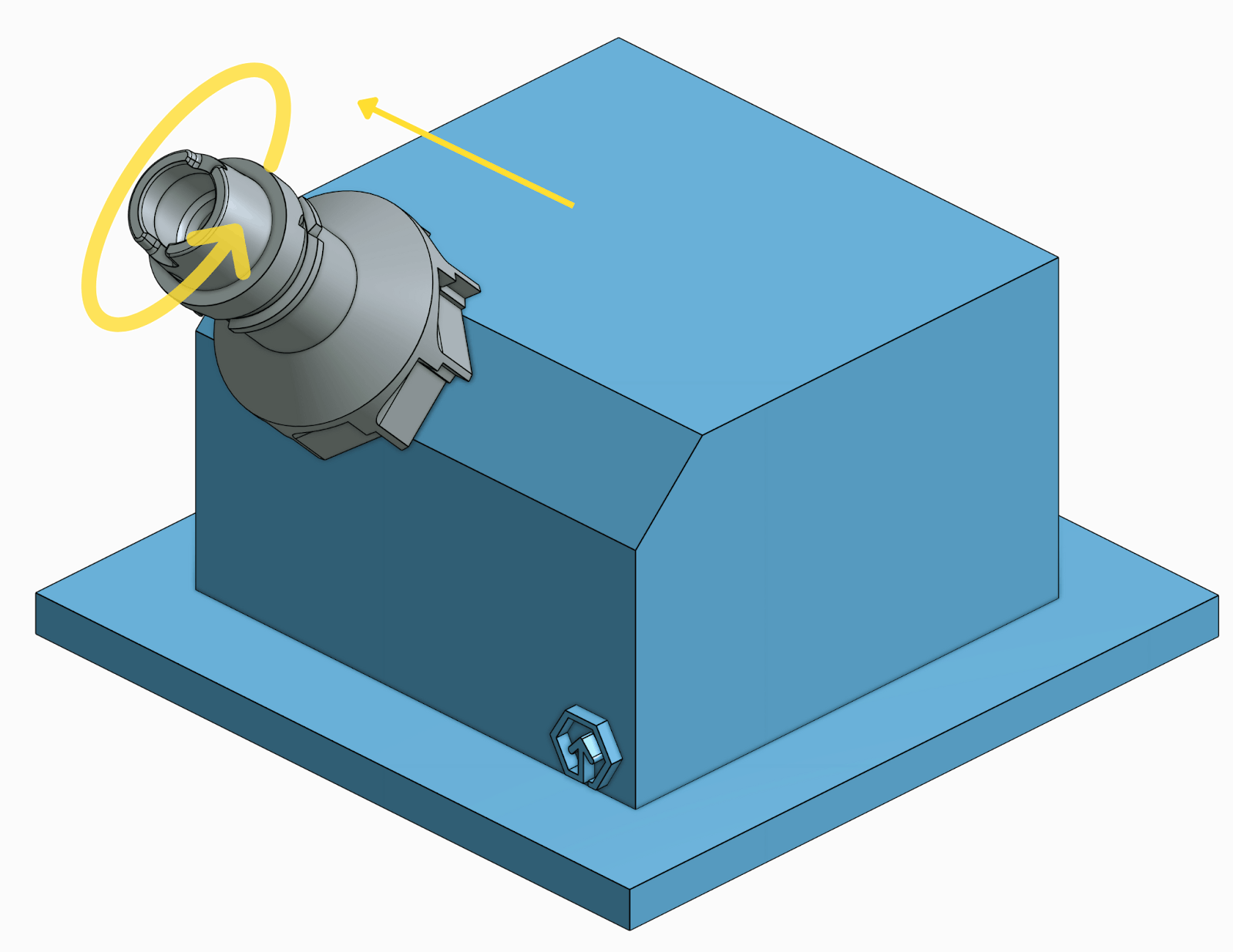
In face milling, the cutting tool's rotation axis is perpendicular to the workpiece. The machine sets the CNC milling cutting tool along the edge of the workpiece by a fixed depth. The cutting tool then moves along the workpiece's surface, removing material from the surface up to the set depth. The cutting tool has teeth at its tip and peripherals. Face milling typically produces flat surfaces and relatively shallow contours.
Plain milling
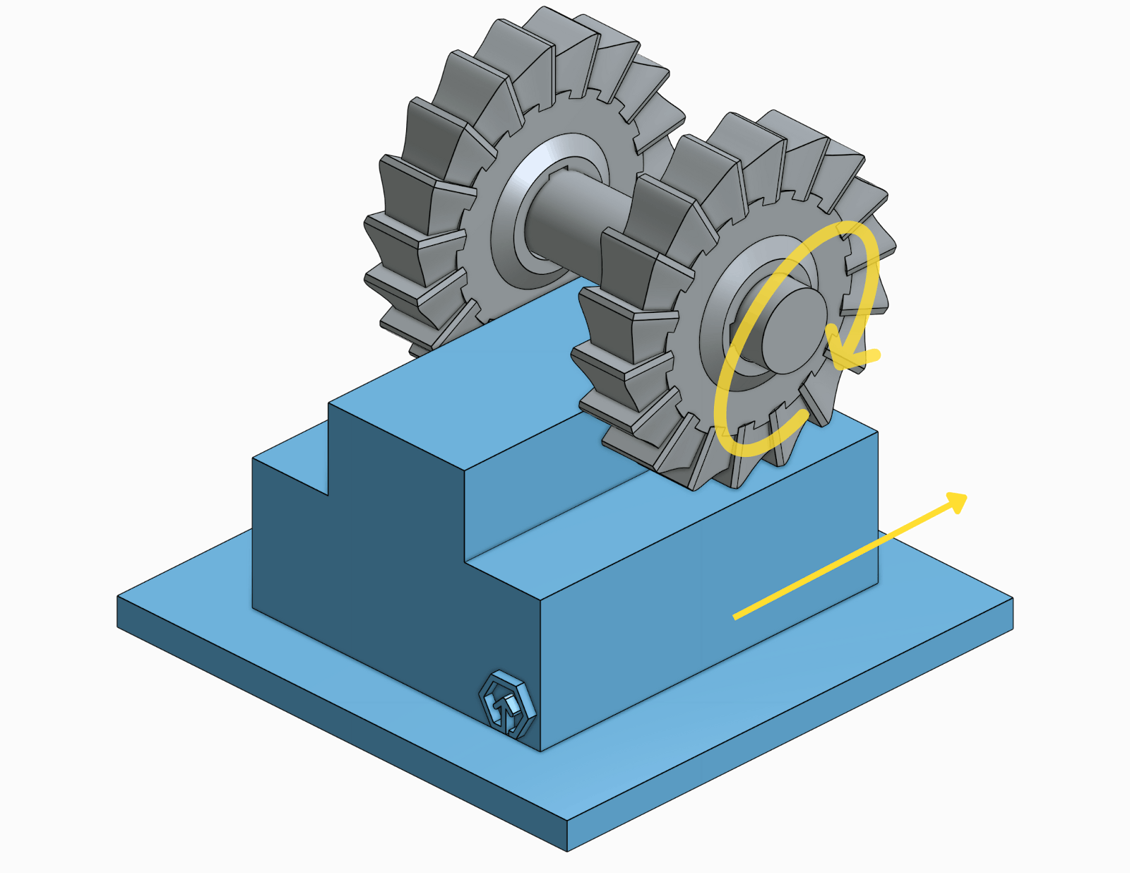
In plain milling, the cutting tool’s axis of rotation is parallel to the surface of the workpiece. The cutting tool has teeth along its circumference for cutting sideways against the workpiece. Plain milling produces features like pockets, cavities, slots, and walls.

Angular milling
Also known as angle milling, this process cuts the workpiece at an angle. The machine sets the cutting tool’s rotation axis at an angle relative to the workpiece's surface. The cutting tool requires teeth at its tip. Angular milling produces angular features such as dovetails, chamfers, grooves, and various other diagonally set features.
Form milling
Form milling involves using specialised CNC milling cutting tools to cut the desired shape into the workpiece. Form milling cutting tools come in specific shapes that correspond to the form of the desired feature. This CNC milling operation produces complex curves, contours, and profiles.
CNC milling material selection
The CNC milling process is compatible with various materials, including wood, acrylic, stone, glass, foam, ceramic, plastics, and numerous metals. Wood, stone, and glass rarely have Industrial CNC milling applications. These CNC milling materials are mainly applied to art, decor, and domestic applications. On the other hand, numerous industries utilise metals and plastics for different products. These CNC milling materials encompass a wide range of elements, compounds, and alloys with varying properties and applications. Geomiq offers an extensive list of the most used CNC milling materials.
These materials have varying properties, making each best suited for different applications. The following are some material selection considerations.
- Work environment: Moisture, pressure, temperature, dust, friction, etc.
- Physical properties: Wear, heat, corrosion, and chemical resistance. Strength, hardness, durability, thermal conductivity, electrical conductivity, etc.
- Purpose: Aesthetics, weight, Finishing options, assembly components, standalone parts, etc.
- Part features
- Cost
See our guide on CNC machining materials to learn more about CNC milling material, their properties, and typical applications.
CNC milling metals
Compatible CNC milling metals include Aluminium, Mild Steel, Stainless steel, Copper, Brass, Titanium, Magnesium, Inconel, Tool Steel, Steel Alloy, Bronze, and their respective alloys.

CNC milling plastics
Compatible CNC milling plastics included ABS, PEEK, Nylon (PA), POM (Delrin/Acetal), Polyethylene (PE), Polyvinyl Chloride (PVC), PMMA (Acrylic), PTFE (Teflon), PPSU, PS (HIPS), and Polyethylene Terephthalate (PET).

CNC milling applications
CNC milling is a highly versatile manufacturing process with various applications across different industries. This process mostly produces small to medium-sized 3D parts with unique or complex geometries. The parts are typically components of a larger assembly but may be end-use standalone parts.
While CNC milling can produce curves, contours, and intricate geometries like engravings, it is particularly useful in producing parametric and cubic geometries. The image below shows some parts manufactured via CNC milling.

Due to CNC milling’s precision and accuracy, industries where part accuracy is crucial, such as aerospace and automobile, rely on this manufacturing method to produce engines, gears, bearings, ducts, and countless other critical parts. Another such industry is medicine and healthcare, where CNC milling produces precise surgical instruments and complex custom devices, such as orthopaedic and cardiovascular implants.
The CNC milling process is also vastly employed in producing standalone objects, fixtures, and parts for industrial equipment and machinery in the manufacturing, production, construction, oil & gas, agricultural, electronics, defence, energy, and mining industries.
CNC milling use cases also extend beyond industrial applications. Non-industrial fields such as woodworking, jewellery making, fashion, and even arts & crafts employ this manufacturing process to create intricate and functional parts. A few examples are custom furniture, personalised gifts, tech accessories, house decor, and custom signage.
The applications of CNC milling fall under three major categories:
- Rapid prototyping
- Custom one-off productions
- Batch production
Rapid prototyping: Rapid prototyping is the process of quickly manufacturing a new part for the purpose of testing its feasibility or functionality. Manufacturers commonly utilise CNC milling for rapid prototyping due to its ability to produce custom parts fast. Geomiq collaborated with Small Robot, an agrotech company in the UK, to speed up their iteration process for prototype designs by providing engineering consulting and rapid custom parts for their robot development.
Custom one-off productions: Many CNC milling applications fall under this category. One example is manufacturing spare parts. If a part in an assembly plant fails during use, engineers can quickly create a replacement part using CNC milling instead of waiting for a replacement from an OEM. Another application is the manufacture of custom parts for specific purposes. For example, CNC milling can create a custom replacement hip for a specific patient.
Similarly, engineers, designers, or artists can create new custom parts from scratch using CNC milling. The same applies to existing parts. A suitable case study for one-off parts is Geomiq's collaboration with Vikaso Robotics. Geomiq regularly supplies one-off custom parts to Vikaso, facilitating innovation and seamless growth.
Batch production: Businesses and manufacturers can utilise CNC milling to mass produce custom or existing parts. These parts may be end-use parts or components in an assembly.
What are the advantages of CNC milling? CNC milling benefits
CNC milling’s widespread popularity is due to its many benefits and advantages. Some of these are as follows:
- Capability: CNC milling is capable of producing a wide range of parts, shapes, features, and complex geometries, from automobile engine parts to intricate furniture.
- Accuracy and precision: With CNC milling, your design is exactly what you get. CNC milling. Milling machines hardly deviate from the 3D model. Note that you have to optimise the model for CNC milling. Furthermore, CNC milling is highly precise and can produce parts with very low tolerances. There's also minimal room for error, as Most aspects of the CNC milling process are computer-controlled, leaving minimal room for error.
- Speed: CNC produces complex geometries fast. This is especially beneficial for prototyping applications.
- Scalability: CNC milling is suitable for both one-off prototypes and medium-scale production batches. This technology can uniformly produce multiple units.
- Material versatility: The CNC milling process is applicable to various materials, including metals, glass, plastic, stone, wood, and many more. If you can procure the material in a block, it is likely milling-compatible.
What are the disadvantages of CNC milling? CNC milling limitations
CNC milling also has some inherent limitations. Some of these are as follows.
- Setup cost: The initial setup costs of CNC milling can be immense. CNC milling machines are relatively expensive; advanced industrial CNC milling machines are only practical for industrial production.
- Speed in large batch productions: While CNC milling can rapidly produce a single unit, batch productions can be time-consuming as most machines can only create one unit at a time.
- Cost of complex geometries: Milling time, effort, and cost increase with the complexity of a part.
- Material wastage: Compared to additive and formative technologies, CNC milling, a subtractive manufacturing technique, generates a significant amount of waste. The material the cutting tool carves away to produce the finished part amounts to scrap.
- Design limitations: A number of features and geometries simply cannot be milled. These limitations inherent to CNC milling include curved holes, extremely thin walls, and straight internal edges. See the CNC milling design tips article to learn more about CNC milling design limitations and optimization tips.
CNC milling alternatives
CNC milling is one of many manufacturing technologies. While this technology has numerous benefits, there are scenarios and applications where other manufacturing methods are better suited. CNC milling is a subtractive manufacturing process. Alternatives are additive manufacturing technologies, such as 3D printing services, and formative technologies, such as casting and injection moulding.. There are also alternative subtractive technologies, such as CNC turning. The following factors determine the best manufacturing technology for your application.
- Material: CNC milling is the most seamless method for manufacturing metals. Formative methods are compatible with metals. However, the process is more complicated, as the metals need to be in the molten state. Metal 3D printing also exists but is less common than its plastic counterpart. 3D printing and formative technologies are more suitable than CNC milling for plastics, as these technologies work with plastics' low melting points. Other materials, such as wood and stone, are only compatible with CNC milling.
- Size: CNC milling is mainly used for small to medium-sized parts. The same goes for 3D printing, as the size of machines available restricts these technologies. Formative technologies, on the other hand, can create small to very large parts.
- Speed: For single units, CNC milling complex geometries fast. Additive technologies also produce parts fast. However, these technologies require extensive setup times for the cast or moulds. For batch productions, on the other hand, additive technologies offer the highest production speeds.
- Precision: Precision varies by the exact technique and machine used. CNC milling offers tolerances of up to ± 0.005″ or 0.13 mm. Some 3D printing techniques also provide very low tolerances.
- Effect on the finished product: The CNC milling process has minimal impact on the physical properties of the part as it processes the part in its default solid state. In 3D printing and formative manufacturing, the materials have to undergo melting. 3D printing also produces parts in layers, impacting the part's structural integrity. Note that finished parts can undergo post-processing to enhance their properties.
- Cost: Cost depends on several other factors and varies significantly with production quantity, part complexity, machine cost, material, and production time and effort.
- Part geometry: Part geometry and features become important considerations when they are critical to functionality. Different manufacturing technologies have varying geometry capabilities and limitations. For example, threaded holes, a seamless feature in CNC milling, cannot easily be replicated with 3D printing. Similarly, undercuts, easily manufactured via 3D printing, cannot be milled.
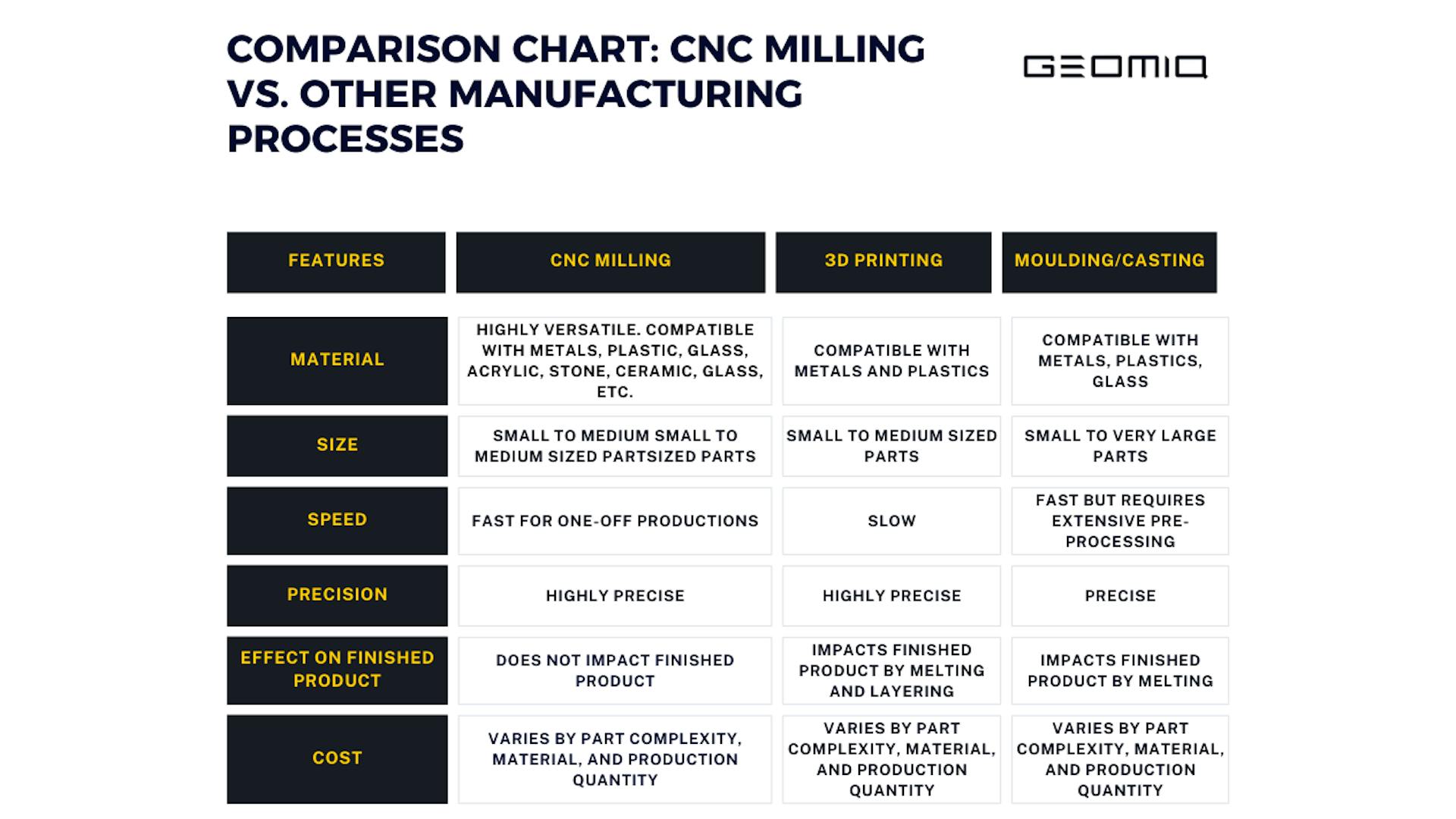
Note that these factors are interrelated. To choose the best-suited manufacturing process for your application, it is necessary to consider the factors jointly rather than deciding based on one factor alone. The table below compares CNC milling with 3D printing and other popular manufacturing processes to help you determine when CNC milling is the best-suited option.
Conclusion
Ready to get started on your CNC milling project? Geomiq is your ultimate partner for all your manufacturing needs. Simply head over to our instant quoting platform and upload your design to get started. With a few clicks, you will receive your finished part in as little as three days. Not sure where to begin? Our team of expert designers and engineers is available to guide you on design, material selection, and custom solutions that precisely match your needs.