Maximizing Efficiency and Performance with FEA Analysis in Modern Manufacturing
Finite Element Analysis (FEA) is a computational tool used by engineers and designers to simulate how a product or structure will behave under various real-world conditions. Whether it’s analyzing the stress on a component, understanding how heat will affect a product, or simulating vibrations, FEA allows designers to predict performance before a physical prototype is ever made. By breaking down complex structures into manageable elements, FEA analysis provides valuable insights into a product's behavior.
This article dives deep into what FEA analysis is, the types of analysis it supports, and its role in manufacturing processes like CNC machining, 3D printing, and injection molding.
What is the Finite Element Analysis?
FEA analysis is a computational technique used to predict how a product or structure will behave when subjected to external conditions such as stress, heat, and vibrations. It involves breaking down a complex structure into smaller, more manageable parts, or "finite elements," and analyzing how each element will react to external factors. These individual results are then combined to provide an overall picture of how the entire system will perform.
Finite Element Modeling (FEM)
The process of creating a model that can be analyzed using FEA analysis is known as finite element modeling (FEM). Engineers use CAD (computer-aided design) tools to create detailed 3D models. These models are divided into finite elements, which vary in shape and size based on the complexity of the design and the type of analysis being performed.
FEA Elements
FEA elements are the smallest parts of the larger structure. These elements can be one-dimensional (like beams), two-dimensional (like plates), or three-dimensional (like solid elements). Each element is tested under specific conditions, and the results are aggregated to simulate the overall behavior of the product.
Key Benefits of FEA Analysis for Engineers and Designers
FEA analysis brings a wide range of benefits, especially when it comes to designing and manufacturing products. By integrating 3D printing services with FEA, engineers can rapidly test and refine designs in a virtual environment before creating physical models. Here are some of the key advantages:
Efficiency in Design Iteration
FEA analysis allows engineers to quickly test different design variations without the need for physical prototypes, accelerating the design process and facilitating faster improvements.
Cost-Effectiveness
By simulating the performance of products digitally, FEA analysis reduces the need for expensive physical prototypes and testing, helping identify design flaws early and saving money on rework.
Improved Product Performance
FEA ensures products meet the required performance criteria by testing components under various real-world conditions, such as stress, temperature, and mechanical forces.
Enhanced Safety
FEA can simulate extreme conditions to identify potential weaknesses in designs, especially important in industries like automotive and aerospace, where safety is a top priority.

How FEA Analysis Works in Different Industries
FEA is widely used across various industries to optimize product designs and ensure they meet safety and efficiency standards. Here's how FEA is applied:
Automotive Engineering
FEA helps simulate crash tests, perform stress analysis on components, and design safer, more efficient vehicles by testing parts for their ability to withstand impact forces and stress.
Aerospace and Aviation
FEA analysis is used to simulate aerodynamic forces and analyze the strength of materials in aircraft design, helping engineers ensure that wings, fuselages, and engines are both lightweight and durable.
Consumer Electronics
FEA is applied in the design of consumer electronics to simulate thermal and mechanical stress. This ensures that parts can handle heat and physical strain, improving product longevity and performance.
Types of FEA Analysis
FEA can perform different types of analysis depending on the specific engineering challenge. These include:
Structural Analysis
Focuses on evaluating stress, strain, and deformation of structures under external forces. It’s essential for ensuring the integrity and durability of designs, particularly in automotive and aerospace applications.
Thermal Analysis
Used to simulate how temperature fluctuations affect materials and structures. This is particularly critical in electronics and automotive industries where overheating can lead to failure.
Vibration Analysis
Determines the natural frequency of a structure and how it reacts to external vibrations. Vibration analysis is key in industries like automotive and aerospace, where products experience dynamic forces.
Fluid Dynamics Analysis
Simulates how fluids (gases or liquids) interact with solid objects. It is used in applications like HVAC systems, automotive engines, and medical devices to optimize fluid flow and performance.

How FEA Works: The Math Behind the Simulation
FEA is not just about running simulations-it's also grounded in complex mathematical formulas that help engineers predict how a product will behave under various conditions. These formulas govern the relationship between forces, displacements, material properties, and more. Below, we’ll cover some of the essential equations used in FEA:
Stiffness Matrix
One of the most fundamental formulas in FEA is the stiffness matrix equation. This matrix represents the relationship between the forces applied to a structure and the resulting displacements. The basic formula is:
{F} = [k] {U}
Where:
- {F} is the force vector (applied forces),
- [K] is the stiffness matrix (material and geometric properties of the structure),
- {U} is the displacement vector (how much the structure deforms).
This equation helps engineers determine how a structure will respond to external forces and is essential for structural FEA.
Element Equations for 1D Elements
For simpler 1D elements, such as beams or rods, the relationship between force, displacement, and stiffness is described by the equation:
F=k⋅u
Where:
- F is the force,
- k is the stiffness of the element,
- u is the displacement.
This equation is typically used for basic simulations and is crucial for understanding the basic mechanics of structures under load.
Thermal Analysis: Heat Transfer
In thermal FEA, the heat conduction equation is used to simulate how heat flows through materials. The formula for steady-state heat conduction is:

Where:
- k is the thermal conductivity,
- T is the temperature,
- x is the spatial coordinate in the direction of heat transfer.
This equation is fundamental in analyzing the effects of temperature on material performance, particularly in electronics and automotive parts.
Stress and Strain Relationship
FEA in structural analysis often relies on Hooke's Law, which describes the relationship between stress and strain in elastic materials:
σ=E⋅ε
Where:
- σ is the stress (force per unit area),
- E is the Young's modulus (material stiffness),
- ε is the strain (deformation per unit length).
This relationship is vital in determining how materials will deform under load, helping to ensure the safety and performance of structures.
Element Stiffness in 2D (Plane Stress)
In 2D FEA, used for triangular or rectangular elements, the stiffness matrix is derived based on the geometry and material properties of the elements. The equation is:
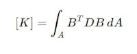
Where:
- K is the stiffness matrix,
- B is the strain-displacement matrix,
- D is the material property matrix (related to Young’s modulus and Poisson’s ratio),
- A is the area of the element.
This formula is important in determining how 2D elements respond to forces and is commonly used in structural analysis, especially for thin-walled components.For a deeper dive into the mathematics behind FEA, including derivations of stiffness matrices and element behavior, explore the MIT OpenCourseWare lecture notes on Finite Element Analysis.

The Role of FEA in Rapid Prototyping and Product Development
One of the main advantages of FEA is its ability to streamline prototyping and speed up the product development process.
Prototyping with FEA
By integrating FEA with 3D printing and CNC machining, engineers can virtually test and refine designs before creating physical prototypes. This combination allows for rapid iteration of designs, ensuring they meet performance criteria. By simulating the product’s real-world behavior, engineers can address potential issues early, which reduces the need for costly physical prototypes and saves valuable time in the product development process.
CNC Machining and FEA Integration
CNC machining services benefit from FEA by optimizing designs for more efficient production. Engineers can simulate the performance of parts before machining them, ensuring that they meet design specifications and reduce machining time and material waste.
Injection Molding and FEA
FEA is also applied to injection molding services. By simulating the molding process, engineers can design molds that ensure uniform material flow and reduce defects in the final product. This is crucial for industries that require high-precision parts, such as the medical and consumer electronics sectors.
Overcoming FEA Challenges
While FEA is an incredibly powerful tool, it does come with its challenges. Here’s how you can overcome them:
- Software Complexity
FEA software can be difficult to use, especially for beginners. However, advancements in user interfaces and cloud-based tools have made FEA more accessible, simplifying the process for engineers at all skill levels. - Computational Power
FEA simulations require substantial computational resources. Cloud-based FEA tools help alleviate this problem, allowing engineers to run complex simulations remotely on powerful servers, reducing the need for expensive hardware. - Mesh Quality and Accuracy
The accuracy of FEA results depends on the quality of the mesh used in simulations. Poor mesh quality can lead to inaccurate results, so engineers need to balance between mesh resolution and computational efficiency to ensure reliable outcomes.
Overcoming FEA Challenges with Streamlined Solutions
By utilizing modern cloud-based FEA analysis tools, engineers can easily overcome these challenges. These tools simplify the process, making FEA more accessible to teams with limited resources. Additionally, CNC machining, 3D printing, and injection molding can be integrated with FEA to improve the efficiency and accuracy of product development workflows.
How FEA Integrates with Manufacturing and Supply Chain Management
FEA analysis isn’t just for designing products; it also plays a crucial role in manufacturing and supply chain optimization.
Optimizing CNC Machining
By integrating FEA with CNC machining, engineers can design parts that are optimized for efficient production. This results in fewer errors, reduced lead times, and lower manufacturing costs.
Injection Molding and FEA
FEA helps simulate the molding process, ensuring that the flow of materials is even and defects are minimized. This is especially valuable in injection molding, where high-precision molds are required to produce parts consistently.
Supply Chain Efficiency
Integrating FEA with manufacturing tools ensures that parts are designed for ease of fabrication, leading to smoother production cycles and reduced delays in the supply chain.
The Future of FEA: Trends to Watch
The future of FEA looks promising, with several exciting trends on the horizon:
- Integration with AI and Machine Learning
AI is increasingly being used to enhance the accuracy and speed of FEA simulations. As machine learning algorithms improve, FEA will become more precise, helping engineers achieve better results faster. - Cloud-Based FEA Tools
Cloud computing is making FEA more accessible to businesses of all sizes. Engineers can now run simulations remotely on cloud servers, avoiding the need for expensive in-house infrastructure. - Increased Automation
FEA is becoming more automated, allowing engineers to run simulations with minimal input. This automation will accelerate product development timelines and improve design efficiency.
Need Help Unlocking the Full Potential of FEA in Product Development? Geomiq Can Help
FEA is revolutionizing design and manufacturing by allowing engineers to test and refine their products virtually. Whether you're aiming to boost performance, cut costs, or speed up production, FEA ensures higher-quality results.
By combining FEA with tools like CNC machining, 3D printing, and injection molding, you can streamline your development process and stay ahead of the competition. Geomiq can help you unlock the full potential of FEA and connect with the right solutions to elevate your projects.
About the author
Sam Al-Mukhtar
Mechanical Engineer, Founder and CEO of Geomiq
Mechanical Engineer, Founder and CEO of Geomiq, an online manufacturing platform for CNC Machining, 3D Printing, Injection Moulding and Sheet Metal fabrication. Our mission is to automate custom manufacturing, to deliver industry-leading service levels that enable engineers to innovate faster.