Mastering GD&T Symbols: A Simple Guide to Geometric Dimensioning & Tolerancing
Geometric Dimensioning and Tolerancing (GD&T) is a critical aspect of modern manufacturing, ensuring that parts fit and function as intended within an assembly. It provides a universal language for engineers, designers, and manufacturers to communicate tolerances, design intent, and the required level of precision. By offering a more flexible and comprehensive approach than traditional dimensioning, GD&T controls size, shape, orientation, and location of part features.
This guide will break down the core principles of GD&T, explain the meaning behind GD&T symbols, and provide practical insights on how to apply them effectively in your designs. We’ll explore the importance of geometric tolerances and demonstrate how mastering GD&T can improve your designs, reduce defects, and streamline your manufacturing processes.
What is GD&T?
Geometric Dimensioning and Tolerancing (GD&T) is an industry-standard symbolic language used to define the size, form, orientation, and location of features on a part or assembly. It allows manufacturers to control part features with precision while maintaining flexibility in design. In industries like automotive, aerospace, and medical devices, GD&T ensures parts meet critical tolerances for safety and functionality. By providing clear guidelines for part design and assembly, GD&T improves efficiency, reduces defects, and lowers production costs.

Key Symbols in GD&T
Understanding the GD&T symbols is essential to reading and interpreting technical drawings. The symbols convey critical information about how parts should be manufactured, inspected, and assembled. Here are some of the most common symbols used in GD&T:

GD&T Symbol Categories
GD&T symbols are grouped into five main categories based on what they control:
- Form (individual feature control)
- Orientation (features relative to a datum)
- Location (feature position control)
- Profile (outline or surface shape control)
- Runout (rotation variation control)
We’ll also cover material condition modifiers and how to read feature control frames.
Form Tolerances
Control the shape of individual features, without referencing other features.
Symbols Covered:
- Ⓐ Flatness

- Ⓡ Straightness

- Ⓑ Roundness (Circularity)

- Cylindricity
Use Cases
- Flatness (Ⓐ): Ensures a surface lies within two parallel planes.
- Straightness (Ⓡ): Controls a line element's straightness (surface or axis).
- Roundness (Ⓑ): Ensures each circular cross-section of a surface is uniform.
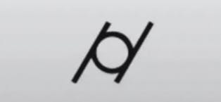
- Cylindricity (/o/): Combines roundness and straightness along a cylindrical feature.

Orientation Tolerances
Control the tilt or alignment of features relative to a datum.
Symbols Covered:
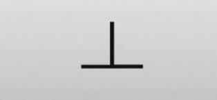
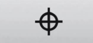
- ⊕ Perpendicularity
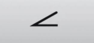
- ⒳ Angularity
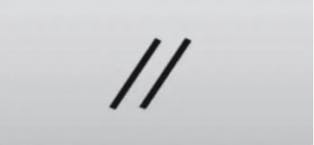
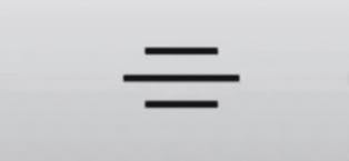
- Ⓣ Parallelism
Use Cases
- Perpendicularity (⊕): Ensures a surface or axis is at 90° to a datum.
- Angularity (⒳): Ensures a surface or axis is at a specified angle (not 90°).
- Parallelism (Ⓣ): Ensures consistent distance from a datum throughout length.

Location Tolerances
Control the position of features relative to datums.
Symbols Covered:
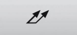
- Ⓙ Position
- Ⓒ Concentricity

- Ⓚ Symmetry
Use Cases
- Position (Ⓙ): Defines exact placement of features (e.g., holes).
- Concentricity (Ⓒ): Ensures centers of two features (e.g., shaft and hole) align.
- Symmetry (Ⓚ): Ensures features are mirrored around a central axis or plane.

Profile Tolerances
Control the shape and contour of features.
Symbols Covered:
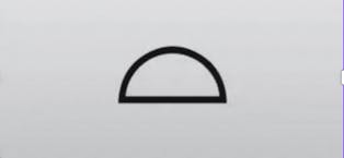
- Ⓟ Profile of a Line

- Ⓠ Profile of a Surface
Use Cases
- Profile of a Line (Ⓟ): Controls a feature's 2D contour in a specific cross-section.
- Profile of a Surface (Ⓠ): Controls the full 3D contour of a surface.

Runout Tolerance
Control surface variation during rotation.
Symbol Covered:
- ⒯ Total Runout
Use Case
Total Runout (⒯): Controls all surface elements of a rotating part across its length.

Material Condition Modifiers
Modifiers specify tolerance behavior based on material limits.
Symbols:
- ⓧ Maximum Material Condition (MMC): Tolerance applies when feature has most material (e.g., smallest hole).
- ⓟ Least Material Condition (LMC): Applies when the feature contains the least material (e.g., largest hole).

How to Read a Feature Control Frame
Feature control frames are the primary symbols in GD&T, used to specify tolerances. Each frame contains information about the type of tolerance, the amount of permissible variation, and any relevant reference information. The structure of a feature control frame includes:
- Geometric characteristic symbol (e.g., flatness, perpendicularity)
- Tolerance value (e.g., ±0.01mm)
- Material condition modifier (e.g., Maximum Material Condition)
- Datum reference (e.g., A, B, C)
Datum reference
Datum references establish a starting point for measurements. They serve as the foundation from which other measurements are taken. Typical datum features include:
- Primary Datum: The main reference for all other measurements.
- Secondary Datum: Used when the primary datum is insufficient.
- Tertiary Datum: The third reference, often used for fine adjustments.
Tolerance zones
Tolerance zones define the acceptable variation for part features. They represent the region within which a feature can exist while still meeting specifications. There are several types of tolerance zones, including:
- Circular Tolerance Zones: For round features like holes or shafts.
- Rectangular Tolerance Zones: For features like slots or grooves.
- Cylindrical Tolerance Zones: For cylindrical parts like pipes or shafts.
Practical Applications of GD&T
GD&T is widely used across various industries to improve the accuracy and quality of manufactured parts. Some practical applications include:
- Automotive manufacturing: Ensuring that car parts like engine components fit and function together.
- Aerospace engineering: Ensuring tight tolerances for parts used in aircraft and spacecraft.
- Medical device manufacturing: Ensuring that medical tools and devices meet strict safety and functionality standards.
How to Apply GD&T in Your Designs
Applying GD&T in your designs involves selecting the appropriate geometric tolerances for each feature and clearly communicating these on your technical drawings. Tools like CAD software often include GD&T symbols, making it easier to incorporate them into your designs. For rapid prototyping needs, it’s essential to understand these principles to ensure the best results in 3D printing service.
UK-Specific Standards for GD&T
While GD&T is based on international ISO standards (ISO 1101), UK industries (referencing BS 8888) may:
- Use stricter tolerance zones, especially in aerospace and medical sectors
- Require more precise datum referencing
- Emphasize use of modifiers (e.g., MMC) in automotive and defense sectors
Tip: Always consult the project-specific drawing standard (e.g., ISO vs BS) when applying GD&T.

Common Mistakes in GD&T
Some common mistakes engineers make when applying GD&T include:
- Misinterpreting symbols or failing to specify the correct tolerance.
- Not properly referencing datum points, leading to alignment issues.
- Overcomplicating designs with unnecessary tolerances.
Avoiding these mistakes ensures that the parts function as intended and meet quality standards.
GD&T and Quality Control
GD&T plays a critical role in quality control by providing clear specifications for inspections. Tools like Coordinate Measuring Machines (CMMs) are often used to check if parts meet GD&T specifications, ensuring that each part fits and functions properly in its assembly. For rapid prototyping, precision in CNC machining and geometrical tolerances is essential to ensure that the prototypes are produced accurately.
This guide has provided a simple yet comprehensive overview of GD&T, covering essential concepts, symbols, and practical applications. By mastering GD&T symbols and principles, you can ensure that your designs meet high standards of quality and precision in manufacturing.
About the author
Sam Al-Mukhtar
Mechanical Engineer, Founder and CEO of Geomiq
Mechanical Engineer, Founder and CEO of Geomiq, an online manufacturing platform for CNC Machining, 3D Printing, Injection Moulding and Sheet Metal fabrication. Our mission is to automate custom manufacturing, to deliver industry-leading service levels that enable engineers to innovate faster.